
> Intro
• Hardware
> Manual
> Terminal
— Projects: UZE, Hardware —
Introduction
In the early Ninties, the German computer magazine c't featured a project to build a small computer around a Toshiba TLCS-Z80 Microprocessor Unit (MPU). The PCB was available at a modest price, i.e. about trice of the MPU itself. A simple software to run it was available for free — printed in the magazine, just type it in, assemble and link it and burn the code into an EPROM.
I developed and built small computers before. They ususally did not work right away and the problem was always: is this a hard- or a software problem? Once, I suspected a software flaw I could not locate. Finally, I replaced the processor by a hardware disassembling logic analyzer (Philips PM3551A) and began to disassemble each instruction. A few minutes later it became obvious that the RAMs were wired up in the wrong mode.
With the CPAC project from c't I hoped that at least the software would work. With a colleague of mine, we bought a couple of PCBs. I built 7 units, all of which worked eventually.
The software sufficed for testing the hardware but was otherwise too limitted. My colleague laid out the bare-bones BIOS on a one-page Nassi-Shneiderman diagram, I did the programming and extended it to make the computer universally usable. Hence the name UZE.
Features
The heart of the comupter is a TMPZ84C015BF-6. It consists of a Z80-CPU (central processing unit), two Z80-SIO (serial input / output), two Z80-PIO, (port input / output) a Z80-CTC (counter / timer channel), a CGC (clock generator / controller), a WDT (watch-dog timer) and a interrupt precedence daisy-chain controller.
32 KB EPROM to store the firmware and 32 KB RAM the dynamic data on board. One SIO used for a RS232C interface, the other one and both PIOs free to interface to any equipment. The full Z80-bus available (unbuffered) to the outside world. The computer runs either on batteries of from a power supply. 5 Vdc is all there is needed.
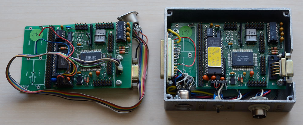
The picture at left shows the board with the processor, RAM and RS232C mounted. This is the unit 7. At right, the developement unit (#3). Here, the EROM covers the RAM. The PCB is mounted in a metallic case and has a push button to activate the non-maskable interrupt (NMI) to reset the processor — the most important control on any computer! For the RS232C, there are 3 connectors: a sub-D 25-pin wired as DTE, a sub-D 9-pin wired as DCE and a special 8-pin DIN, which is the UZE standard. (I am a bad and impatient mechanic. Drilling a hole for a connector is preferred to filing square holes that are always too large, no matter how long you file.) Another round DIN connector is used to feed external power to the unit. Batteries are not used and a piece of the PCB was cut out to get room for the UZE DCE connector. The whole mess runs at 4 MHz.
Keyboard and Display
None! The UZE connects to any host computer via a RS232C connection: 9600 Baud, 8 data-bit, 1 stop-bit, no parity. This is the boot-up default configuration. Instead of connecting a host directly to the UZE, a modem over a telephone line works just as well. The host computer acts as a terminal. There is no need to use a 1 GHz Pentium IV computer, but it will also nicely do.
© 2004 - 2018 by Horo Wernli.