
> Intro
• Overview
— IBL and HDRI: HDRI for IBL, Overview —
Introduction
What does HDRI and IBL stand for anyway?
HDRI does not need IBL but IBL needs an HDRI and such in the form of a panorama
which can be projected inside a sphere. IBL stands for Image Based
Light, HDRI for High Dynamic Range Image.
IBL is a natural way to light a scene generated by a simulator — a raytracing program. Without IBL, the scene is lit by a sun and possibly several additional light sources. Even though the light sources seem to have a size, the raytracer considers them as one dimensional points and it cannot follow and calculate rays from such a dot. This means that it is not possible to show reflections from a light source on a body.
Therefore, the spectacularity channel was introduced which simulates the reflection of a light source on an object and gives it some quality of glossiness. If the scene is rendered in IBL mode, the specularity channel is not so important anymore because the picture used for lighting is not a one dimensional point but it is all around the scene and the raytracer can follow the light and calculate the reflection on the body lit by it.
The computer screen shows pictures with a contrast of 1:256 for each colour red, green and blue. The contrast or dynamic range of light nature has to offer is in the range of 1:2 billions (2,000 millions). The photograph shot with a digital camera also has a dynamic range of only 1:256. If the picture is saved in the raw format, it may have a range of up to 1:65,536. The HDR format saves pictures with a dynamic range of 1:4 billions for each of the three colours.
To view a picture stored as HDRI, a special viewer program is needed. With such a viewer, you can browse along the stored intensities to have a part of it displayed.
Pictures with a dynamic range of tens or hundreds of thousand can be used as light sources for IBL to light a scene. The room is assembled around the table with the vase on it and the landscape with sky and ground in an outdoor scene. Imagine the object, the camera and the observer are in the centre of a sphere. On the inner face of the sphere, the HDRI is projected and thus lights up the inside of the sphere. That is why a special panorama is needed for the HDRI.
Under the topic «3D World» the creation of cylindrical, spherical and cubical panoramas that are made to view as animated QTVR movies is discussed. Here, panoramas are used for something different. Therefore, we will have to contemplate again the creation of panoramas but such that can be used for HDRI and IBL. We will also have to think about what size and resolution the HDR panorama should have to be useful for the purpose.
Projections for panoramas
There is more than one way to create panoramas that can be projected on the inner wall of a shpere. They are shown here. A normed scene is used to make the difference of the methodes more obvious.
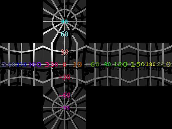
A cage was constructed in Wings3D. The ribs follow each other at an angle of 30°, horizontally as well as vertically. The numbers that show the angles were created with Elefont.

A single radial light is placed a bit left, above and forward of the centre and is solely responsible to shed some light on the setup. The cage is set into a large sphere onto which the cage casts shadows.
According to the method used, either the camera or a mirror ball is set in the centre of the cage.
The picture shows the overview of the setup. The camera was placed outside the outer sphere which was set to 75% transparency.
Cubical Methods
A cubical panorama consists of the six faces of a cube which are rendered separately. The camera is located in the centre, its angle of view is set to 90° and the document has a square aspect ratio (Bryce: FOV = 90°, Size = 72.5%). A render is made from each of the camera rotation settings at 0°, 90°, 180° und 270°. Then, the camera is rotated back to Y = 0° and another two renders are made with the camera tilted up (X = -90°) and down (X = 90°). In this way, the four faces, the top as well as the bottom faces of the cube are rendered.
From the six faces of a cube, a cubical QTVR movie can be created. This is not needed here to project the panorama on the inner side of a sphere. Some converters cannot handle six different pictures and they need a single one. The separately rendered pictures have to be arranged in a certain manner into a single picture using a graphics application.
The picture above shows the six rendered cube faces assembled into the horizontal cross cube format. The individual pictures must be put one next to the other seamlessly. Here, a small gap was left to show how the horizontal cross was assembled.

Other programs expect a vertical cross cube. Such a one is showed above. The only difference between the HCF (horizontal cross cube format) and the VCF (vertical cross cube format) is the position of the cube's backside (or south side). It makes the foot of the cross and is rotated by 180°.
You hve to imagine how this cube was unwound (UV mapped) to comprehend why the back side has to be upside down. Here, too, the individual pictures must be assembled without seams, not with gaps as shown at left.
The Mirror Ball Method
Here, the reflection of the environment on a mirror sphere is recorded. In the scene, such a mirror ball replaces the camera, which is moved back. The method with the mirror ball can also be used to create a panorama with a photographic camera. Anyway, this is the cheapest way to do it. If a scene is rendered, the cubical method should be given preference over the mirror ball variant.
To get the same resolution with a mirror ball as with the cubical method, the diameter of the sphere must be set 2.773 times larger than the length of a cube edge. An area 27.3% larger than the utilizable surface — the sphere's disk — has to be rendered. These are disadvantages.
A free standing sphere does not only mirror what is in front of it but what is behind of it as well. However, the part behind it is mirrored at its edges and there is less space for a certain area to be mirrored than for the environment facing the sphere. And the sphere itself also covers a part of the environment and this is shown as a black spot.
The smaller the diameter of the mirror ball, the smaller the black spot — and the smaller the area the part behind the sphere has to be packed into. If a mirror ball is used in photography, the camera and the photographer are depicted in the best quality.
Therefore, more than one photograph is taken from the reflections on the sphere. Move the camera along an imaginary circle around the mirror ball and take another shot from its sides. Even if a scene is rendered using a mirror ball, the camera should assume more than one position and take renders. When there are two or three photographs, photographer, camera and tripod can be removed from the final panorama. The parts with low resolution and quality can be replaced by better representations taken from another angle.
Another important note: the camera should be placed as far away from the mirror ball as possible. For one, camera, tripod and photographer become smaller relections and are thus easier to get rid of. Secondly, the camera angle of view should be set as narrow as possible. Use the best tele lens you have got, set it to full zoom and move the camera so far away that the mirror ball just fills the picture. Set FOV for the Bryce camera lower than 10°.
Four renders of a mirror ball. Of course, the pictures are mirrored, what else could you expect from rendering a reflection? The camera was placed at four different positions around the sphere and a picture was rendered.

The distortions at the edges are obvious. With the four renders of the mirror ball from different directions, the panorama can be corrected. In this mirror ball projection, this would be very difficult, indeed. Therefore, these projections will be transformed into a more convenient one later.
The Sky Dome
Sky domes can be photographed directly using a fisheye lens. The camera lies on the ground and looks straight at the sky in the zenith. A panorama created this way is incomplete but may suffice nicely for certain applications. What is missing is the part below the horizon, the nadir, only the part above the horizon to the zenith is shown.

With Bryce, too, a sky dome panorama can be created in one go. Place a mirror ball on the ground, move the camera high up and tilt it down (X = 90°). The camera should be high up and the FOV small as for a mirror ball panorama. Also, the document should be square. The only difference is that the camera is tilted down by 90°. The ground appears on the mirror ball as well but the part below the horizon will be cut out later and the picture tilted back into the horizontal plane.
Recap
Panoramas that can be used for IBL can be created by different means. Cubical environments are created by the six faces of a cube and the individual pictures are assembled to either a horizontal or vertical cross. This is the best method to create a panorama in Bryce: the quality is highest, the time to render shortest and only few additional work in a graphics program is needed.
The methods with the mirror ball and the sky dome are the cheapest way to get to panoramas with a digital camera. These methods can be used with Bryce as well. They need a lo of time and additional labour, though.
In fact, there is still more work to be done. First, the pictures have to be corrected. And we still have not yet got an HDRI — we have only learned how an appropriate panorama can be created. To obtain an HDRI, several photographs or renders are needed. This means that the whole labour to correct the pictures will be multiplied. Later, differently lit panoramas will be combined to an HDRI.
© 2004 - 2018 by Horo Wernli.