
< 3D World
> Intro
> Overview
> Create
• Bryce
— 3D World: Anaglyphs, Bryce —
Anaglyphs with Bryce
If you have read through thre previous three chapters, you should be able to create anaglyphs with Bryce withourt problems. Here, the steps necessary are summarised especially for Bryce.
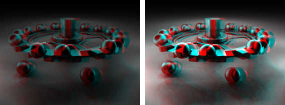
The camera should neither be rotated in the Y- or Z-axis and it is better when the X-axis is at 0° as well. If the camera is tilted or pitched, the result is less predictable. Here, the example picture.
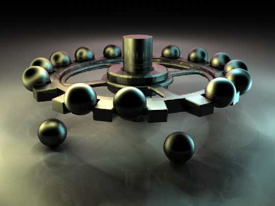
We are going to create an anaglyph from this picture. Two separate renders will be needed. Since the picture is so nicely centered, we will move the camera left and right. Of course, we could always declare the original picture as either the left or the right component. Then, only one render for the other eye has to be created.
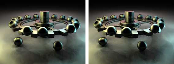
Here, we will make two renders. From the current camera X-position, we subtract 2.5 Bryce Units (BU); if the camera is at 0.00, it will be moved to -2.50. Thus, the camera is moved to the left. Now the scene is rendered and the picture saved as picture-left.tif.
Then, the camera will be moved by 5 BU to the right. Then it is 2.5 BU right of the center. Render the scene from this point of view and save the result as picture-right.tif.
Bryce can now be closed, it is not needed anymore since we have got two pictures — one for the left and one for the right eye.
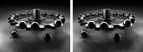
In the graphics application, both pictures are converted to monochrome (Mode: Greyscale).
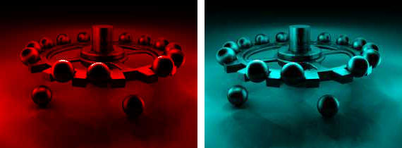
The mode will be set back to RGB-Color. This means that the greyscales pictures become monochrome colour pictures. Remove from the left picture all green and blue colour components to get a red-monochrome picture.
Remove all red components from the right picture to get a cyan-monochrome picture.
Position the right cyan picture over the left red picture and set the transparency to 50%. How this has to be done in the graphics program used cannot be shown. Each program is different.
The resulting picture is too dark. The histogram shows the brighness only to half of its range. Brihtness and contrast of the picture have to be adjusted with the graphics program. Then, the anaglyph is done.
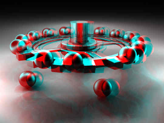
We have the anaglyph. If you have red-green anaglyph-goggles, you may want to remove from the right picture the blue components as well. For red-blue glasses, remove the green components from the right pictures as well. Goggles with red-cyan glasses are preferable because all colour components are contained in the picture.
Depending on the distance of the objects from the camera, you might have to use different values to move the camera sideways. The suggested ±2.50 BU is a good starting value. You may have to decrease the X-distance. If you chose longer X values, the 3D effect gets more pronounced — sometimes, this will prove to be too much and instead of seing one 3D picture, two seperate pictures are perceived.
 |
Note: «Lenses» can be bolted onto the Bryce camera. This makes it possible to render an anaglyph in Bryce 7.1 directly in one go. Commercial: At left the product Bryce 7 –
Pro True 3D Rendering by David Brinnen und Horo, available in our
on-liine shop at Daz 3D: It contains the ALS (Anaglyph Lens System), ALST (ALS Target), ALST_Crossover, ALST_Parallel, ALST+ and PALS+ as Bryce objects. 16 videos, 4 PDF-documents, examples, … |
© 2004 - 2018 by Horo Wernli.