
> Intro
> Overview
> Fisheye
• Mirror Ball
> Cube
> Light
> Filter
> Plugins
— IBL and HDRI: HDRShop, Mirror Ball —
Combine pictures from a Mirror Ball
How photographs made from two sides of a mirror ball are equalised is discussed in 3D World > Mirror Ball. Here we cover how all this can be done in HDRShop. We already have two assembled HDRIs that were taken at about 90° around the ball. Also, we have them cropped already.
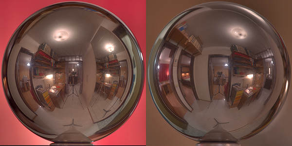
The diameter of the ball at right is 63 pixels wider than the one at left, something that is not obvious here. This difference will be compensated for when both photographs from the mirror ball are transformed into the spherical projection and giving both the same size. Image > Panorama > Panoramic Transformations…
Hint: If Use Suggested Aspect Ratio is ticked, the size of only one side has to be entered, the other one is filled in automatically. However, if you wish another aspect ratio, you have to untick that option.
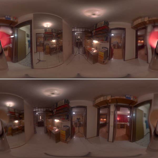
Both mirror ball photographs in the spherical projection; left and right already swapped, i.e. «de-mirrored». It is quite apparent that brightness and tint are not the same for both pictures. That is already so with the originals and has nothing to do with the tone-mapping and we will have to care about that later. One of the pictures has to be shifted in such a way that it gets congruent to the other.
Both pictures are opened in HDRShop. The Points window at right opens when you click on Window > Point Editor.
The coordinates of the reference points set in a picture are listed in this window. Here, I copied the coordinates of the second picture into the field. To set a reference point: hold down [ctrl] key and click with the left mouse button on the appropriate spot in the picture.
We can either define two points in picture 1 and then the corresponding two points in picture 2 or we can define the first point in both pictures and then the second in both. The coordinates shown in the Point Editor are always from the active picture. You have to put the focus to the picture from which you want to see the coordinates.
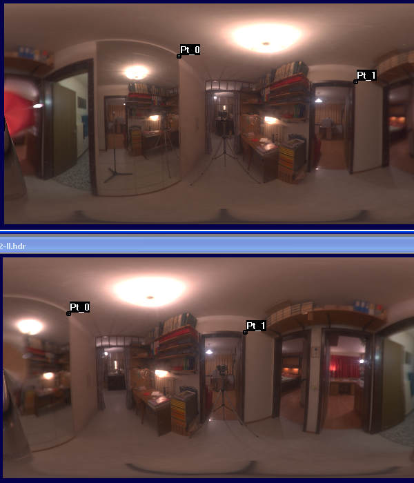
Both pictures with the reference points set. The coordinates in the Points Editor are only shown — you have to note them down for the next step! The lower picture will now be moved in such a way that it alignes with the upper. There are two methods how this can be accomplished.
The classical method
Image > Panorama > Panoramic Transformations… opens the
dialog. Source Image is the second, as Destination Image we want a new
one. The source image is in the Latitude/Longitude projection, the new
one shall be in the same projection and with the same size as well. Now
activate the Match Points button and click on Settings [1].
The Match Points dialog pops up. On the left hand side, the parameters for the picture to be shifted are entered, on the right hand side those for the reference picture. Luckily, we have noted the coordinates of the reference points in both pictures from the Points Editor. Do not forget to set the Assuming Format for both pictures. All fields need attention. Accept the entries [2]. Back in the main dialog, check the parameters and accept them as well [3]. After a moment, the new picture appears.
The alternate method
You can content yourself with only defining one reference point in
each picture and only use the X coordinate. Knowing these, we can
calculate the number of pixels one picture has to be shifted to
align with the other. In our example P0-X picture 1 = 1013.5, P0-X
picture 2 = 380.5, difference 633. Since the pictures are 2560 pixels
wide we can calculate that the camera was moved by 89° around the
ball.
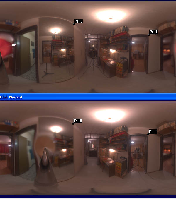
Image > Transform > Shift w/Wrap… opens a small window. The active picture can be shifted right and what disappears at right reappears at left. Likewise a picture shifted down has the shifted-out part appearing on top.
The first picture shall be shifted by 633 pixels to the left — only there is no left option left. Therefore, it has to be shifted by 2560 - 633 = 1927 pixels to the right. Alternately, instead of shifting picture 1 we could shift picture 2 by 633 pixels to the right.
Shifting is done directly on the selected picture! If you remember how much you had shifted, you may always continue shifting it in the same direction until it is shifted one full width or height.
Whichever method was used, we arrived at two congruent pictures with only the camera and the Blind Spots at different places.
Colour and Brightness Correction
This is a bit of a trial and error sort of thing asking for a lot of
patience. Sometimes it works like a treat and sometimes you are driven
to dispair. Perhaps somebody comes up with a more reliable method. I
move the mouse to a particular spot in picture 1 and note down the RGB
values which are displayed in the status line. Then I move the mouse to
the corresponding pixel in picture 2 and write down those values as well.
In this manner, I note three to five points, add the individual colour values for each picture and then calculate the factor of difference for each colour in both pictures. Using these factors, all pixels in one picture are scaled.
Here you find the dialog needed for this: Image > Pixels > Scale… In the Scale Pixels by dialog the calculated factors can be entered. The active picture is subjected to the correction. It is recommended to save the picture prior to experimenting, because you hardly get it right at the first attempt.
Crossfade Pictures.
Once both pictures show about the same brightness and hue, it is time
to combine them. The good bit of each picture shall contribute to a new
one, i.e. without camera and Blind Spot. To accomplish this, we need a
crossfade mask. Such can be created in any graphics application and
saved as BMP. Mask used and the result optained are shown farther down.
Now first how it is done: Image > Calculate opens the dialog shown
below.
Image A is the first and Image B the second picture, Image C is the crossfade or alpha mask. This is my asymetrical 2560 x 1280 pixel alpha mask. We want a New Image for the Destination Image and for the Operation we select A * C + B * (1-C).
What is going on with this function? The white part of an alpha mask is transparent while the black part is opaque. The new picture will be made of the parts of the first picture (A) that lie under the white part of the mask (C), and those parts from the second picture (B) that lie under the inverted mask (C -> 1-C). Whatever is defined as Image D does not matter, it is not used by this function. The following, long picture shows what happens.
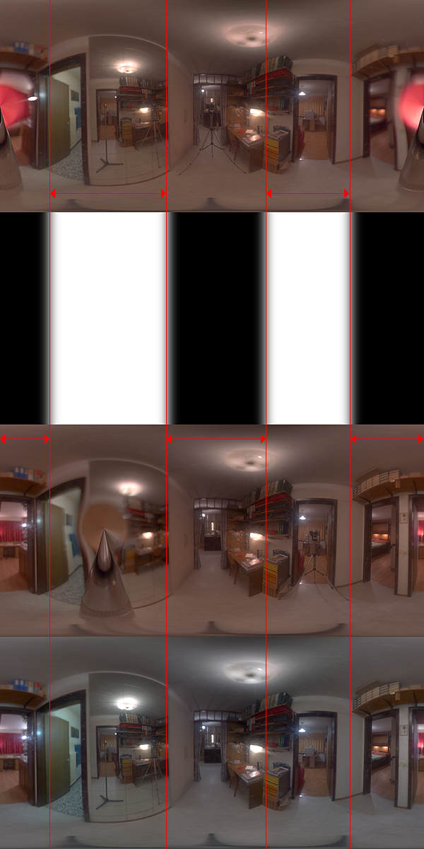
On top the first picture Image A, below it the alpha mask Image C, followed by the second picture Image B and at the bottom the result after white balancing. The red lines show where the pictures crossfade. Camera and Blind Spots disappeared in the resulting picture. However, there are still the camera and the mirror ball visible in the mirror…
White Balance: First, select an area that ought to be white. Move the mouse over the area, depress the left mouse button and mark the selection. On the small desk beneath the lamp there is a white sheet of paper.
Note: If you cannot mark a selection, i.e. no white dotted rectangular appears, you must save your work (you ought to do this regularly anyway), quit HDRShop, restart HDRShop and open the picture. That makes selection work again.
When you have a selection, click on Image > Pixels > White-Balance Selection. HDRShop takes the selected part of the picture and calculates the factor to multiply the red, green and blue pixels by to get the selection white and applies these factors to all pixels in the picture.
The example looked a bit overly cold after the white balancing; after all, there is quite some yellow artificial light around. I corrected this manually: Image > Pixels > Scale… Red 1.1, Green 1.0 Blue 1.0. That was not enough, so on a second iteration I left Red at 1.0 and set Green and Blue to 0.9 each.
The HDRI is still in the spherical projection. If you take this business really seriously, you might consider removing the rest of the tripod visible at the lower edge. You will need a graphics tool able to handle HDRI's because this cannot be done in HDSRshop.
This picture can be transformed to a Light Probe for Bryce 6 IBL.
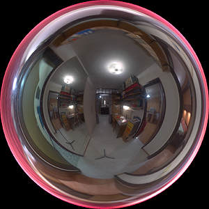
Above the finished light probe — without the tripod removed, though. It is exactly at the nadir.
© 2004 - 2018 by Horo Wernli.